Reading data from a Modbus RTU sensor is one of the most common tasks in industrial data acquisition. The process is simple once you understand the key parameters and register configuration.
1. Identify the Sensor’s Communication Settings
Before reading any data, confirm these parameters from the sensor manual:
- Slave address (e.g., 1, 2, 10, 50)
- Baud rate (9600 or 19200 recommended)
- Data bits / parity / stop bits
- Register map
If any value is wrong, the sensor will not respond.
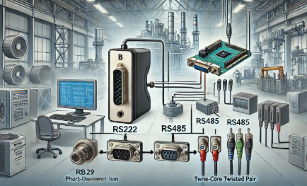
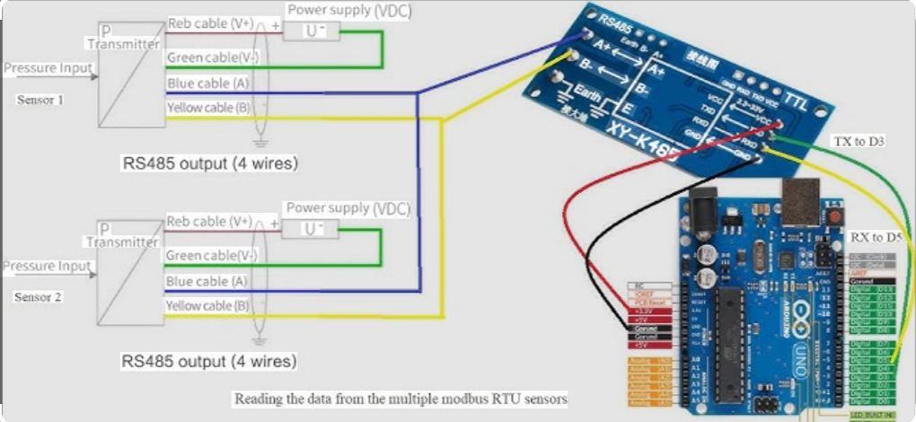
2. Connect the RS485 Bus Correctly
Ensure proper wiring:
- A to A
- B to B
- Termination resistor enabled
- No star topology
Stable wiring is essential for accurate readings.
3. Determine the Register Type
Most sensors store their values in:
- Input Registers (30001+)
- Holding Registers (40001+)
Typical examples:
- Temperature: 30001
- Pressure: 30002
- Humidity: 30003
Refer to your device manual for exact mapping.
4. Read the Register Using a Modbus Master
Use any Modbus master software or your DAQ platform to read:
- Function Code 03 (Holding Register)
- Function Code 04 (Input Register)
Specify:
- Register address
- Quantity
- Device ID
If communication is correct, the sensor will return raw register data.
5. Decode the Returned Value
Many sensors use:
- INT16
- UINT16
- FLOAT32 (two registers, specific byte order)
Example:
If the sensor returns a FLOAT32 across two registers, ensure correct byte swapping (ABCD, CDAB, BADC, etc.).
6. Verify the Value Against Real Measurements
Finally, compare the readings with:
- A physical meter
- Manufacturer’s reference values
This confirms data accuracy before deploying your DAQ system.