Modbus RTU uses a simple register-based structure, but many engineers still get confused when integrating new sensors, meters, or PLCs. Understanding register types is essential for accurate data acquisition.
1. The Four Modbus Register Types
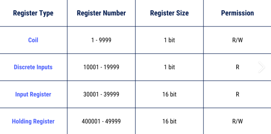
Modbus defines four primary data areas:
- Coils (00001–09999)
- Read/Write
- Digital outputs (ON/OFF)
- Discrete Inputs (10001–19999)
- Read-only
- Digital inputs (status signals)
- Holding Registers (40001–49999)
- Read/Write
- Parameters, counters, analog values
- Input Registers (30001–39999)
- Read-only
- Sensor measurements (temperature, pressure, energy)
Most industrial sensors use Input Registers or Holding Registers.
2. Common Data Formats
Register values may use different formats, including:
- INT16 (single register)
- UINT16
- INT32 / UINT32 (two registers)
- FLOAT32 (two registers, byte order required)
- BCD
To decode correctly, always check the device’s Modbus manual.
3. Addressing Differences: 0-Based vs 1-Based
Some manuals use:
- 0-based addressing (address 0 = 40001)
- 1-based addressing (address 1 = 40001)
If your readings look wrong, check the addressing mode.
4. Polling Frequency Matters
Polling too fast causes:
- Communication timeout
- CRC errors
- Bus overload
Typical stable polling rates:
- Sensors: 200–500 ms
- Meters: 1–2 seconds
- PLCs: depends on scan cycle
5. Always Validate Registers Before Deployment
Before integrating into your DAQ platform:
- Read a few registers
- Compare values with real measurements
- Confirm byte order for 32-bit data
This prevents incorrect data mapping in production.